
The wheel loader, often called a front-end loader, bucket loader, or scoop loader, is an indispensable piece of heavy equipment on construction sites, in quarries, lumberyards, and agricultural operations worldwide. Its primary function is to scoop, lift, and transport loose materials such as dirt, sand, gravel, rock, debris, or snow. But beyond its seemingly simple task, a loader is a marvel of engineering, integrating complex mechanical, hydraulic, and electrical systems to deliver immense power and precise control. So, how does a loader work?
Understanding a loader's operation involves dissecting its core components and how they seamlessly interact. This article will delve into the technical intricacies of how a wheel loader functions, examining its power source, powertrain, hydraulic system, steering mechanism, and the role of its working attachments. We'll illustrate these principles using examples like the robust b30 wheel loader and the agile Q36 wheel loader, highlighting how their design enables them to efficiently tackle diverse material handling challenges.
1. The Powerhouse: Engine and Fuel System
At the heart of almost every modern wheel loader is a powerful diesel engine. These engines are chosen for their high torque output at low RPMs, which is crucial for the demanding tasks of digging into dense material and lifting heavy loads.
Combustion Process: Diesel engines work by compressing air to a very high temperature, then injecting diesel fuel into the compressed, hot air, causing it to spontaneously ignite. This combustion generates immense pressure, driving pistons and ultimately rotating the crankshaft.
Fuel System: A sophisticated fuel system ensures precise fuel delivery, including a fuel tank, pumps, filters (to remove contaminants), and injectors that atomize the fuel for efficient combustion.
Cooling System: Given the heavy loads and continuous operation, an efficient cooling system (radiator, fan, coolant) is vital to dissipate heat and prevent engine overheating.
Air Intake and Exhaust: Air filters protect the engine from dust and debris common on job sites. The exhaust system manages combustion byproducts, often incorporating emissions control technologies to meet environmental regulations.
For example, a smaller Q36 wheel loader (likely around 1.5-ton capacity) would feature an engine optimized for its size, balancing power with fuel efficiency for lighter tasks. A larger b30 wheel loader (possibly a 3.0-ton or higher capacity, though "B30" can also refer to certain compact articulated forklifts, if it refers to a wheel loader it would imply a robust, substantial machine) would house an even more powerful engine capable of generating the force needed for greater breakout and lift capabilities.
2. The Drive System: Powertrain and Traction
The powertrain is responsible for transmitting the engine's power to the wheels, enabling the loader to move and apply force.
Torque Converter: This fluid coupling connects the engine to the transmission. It allows the engine to continue running even when the wheels are stopped, providing smooth power transfer and multiplying torque, which is essential for digging into piles without stalling the engine.
Transmission (Gearbox): Most modern wheel loaders utilize a powershift transmission, allowing operators to shift gears smoothly under load without fully disengaging the clutch. This transmission provides multiple forward and reverse gears, allowing the operator to select the appropriate speed and torque for different tasks (e.g., lower gears for digging and pushing, higher gears for travel). Some advanced loaders use hydrostatic or hybrid powertrains for even finer speed control and efficiency.
Drive Shafts: These shafts transmit power from the transmission to the axles.
Axles and Differentials: Heavy-duty axles house gears that distribute power to the wheels. Differentials allow wheels on the same axle to rotate at different speeds during turns, improving maneuverability and preventing tire scrub. Many loaders have four-wheel drive (4WD) for superior traction on uneven or slippery terrain.
Wheels and Tires: Large, robust tires with aggressive treads are critical for traction, stability, and load-bearing capacity on diverse surfaces, from asphalt to loose gravel and mud. The size and type of tire are carefully selected based on the loader's intended application.
When a Q36 wheel loader maneuvers around a tight landscaping project, its compact powertrain allows for precise, responsive movements. In contrast, the b30 wheel loader, handling heavier loads, would rely on a more substantial powertrain to deliver robust pushing power and stable transport capabilities across potentially challenging ground conditions.
3. The Muscle: Hydraulic System
The hydraulic system is arguably the most critical component that enables a loader to perform its work. It converts the engine's mechanical power into hydraulic power, which is then used to actuate the lift arms and bucket.
Hydraulic Pump: Driven by the engine, the pump (often a gear pump or piston pump) draws hydraulic fluid from a reservoir and pressurizes it.
Hydraulic Reservoir (Tank): Stores the hydraulic fluid, keeping it cool and clean.
Control Valves: These valves are operated by the operator (via joysticks or levers in the cab). They direct the high-pressure hydraulic fluid to specific cylinders. Modern loaders often use load-sensing hydraulic systems, which only deliver power when needed, improving fuel efficiency. Pilot controls (hydraulically or electronically actuated) often provide a smoother, more precise feel for the operator.
Hydraulic Cylinders: These are the "muscles" of the loader. They consist of a cylinder barrel and a movable piston rod. When pressurized hydraulic fluid enters one side of the piston, it pushes the rod out, and when fluid enters the other side, it retracts the rod.
Lift Cylinders: Connected to the main lift arms (boom), these cylinders raise and lower the entire loader assembly.
Tilt Cylinders: Connected to the bucket, these cylinders control the "curl" (tilting back to scoop or hold material) and "dump" (tilting forward to release material) actions of the bucket.
 Hydraulic Lines and Filters: Hoses and pipes transport the hydraulic fluid throughout the system, while filters ensure the fluid remains free of contaminants, which are vital for the longevity of components.
When an operator on a b30 wheel loader pulls back on the joystick to lift a full bucket of aggregate, the hydraulic pump sends high-pressure fluid through the control valves to the lift cylinders, extending them with immense force. Simultaneously, a slight curl action, controlled by the tilt cylinders, keeps the material securely in the bucket. The precision of this system is what allows operators of even compact machines like the Q36 wheel loader to perform fine grading tasks or carefully load delicate materials.
4. Direction and Maneuverability: Steering System
Most modern wheel loaders employ articulated steering, which is a key differentiator from rigid-frame vehicles.
Articulation Joint: The loader's chassis is divided into two main frames (front and rear) connected by a central pivot or articulation joint. This joint allows the front and rear sections to pivot relative to each other.
Steering Cylinders: Hydraulic cylinders are connected across the articulation joint. When the operator turns the steering wheel or joystick, hydraulic fluid is directed to these cylinders, causing them to extend or retract, effectively "bending" the loader at the waist.
Advantages of Articulated Steering:
Tight Turning Radius: Allows the loader to maneuver in much tighter spaces than a rigid-frame machine of similar size.
Improved Traction: During a turn, all four wheels maintain contact with the ground, maximizing traction.
"Crab Steer" Effect: In some conditions, the operator can use articulation to "crab" the machine, pushing material against a wall while maintaining a parallel path.
The Q36 wheel loader, being a mini-loader, benefits immensely from articulated steering, allowing it to navigate confined construction sites or narrow farm roads with ease. The b30 wheel loader, even with its larger size, utilizes this same principle to perform efficient load-and-carry cycles in busy material yards or tight quarry benches, maximizing productivity.
5. The Working End: Attachments and Their Interaction
While the bucket is the standard attachment, a loader's versatility is greatly enhanced by its ability to swap attachments.
Quick Coupler (Optional): Many loaders feature a hydraulic quick coupler, allowing operators to rapidly switch between different attachments (e.g., forks, grapples, snow plows, brooms, rippers) from the cab, dramatically increasing the machine's utility.
Bucket Types: Different bucket designs exist for specific materials: general-purpose, rock, light material, multi-purpose, etc. The choice of bucket optimizes efficiency for the specific task.
The operator interacts with all these systems through the controls in the cab, typically a steering wheel or joystick on the left, and a multi-function joystick on the right for the loader arms and bucket. Pedals control acceleration and braking.
 The Operational Cycle: A Coordinated Flow
Putting it all together, a typical loading cycle demonstrates the integrated function:
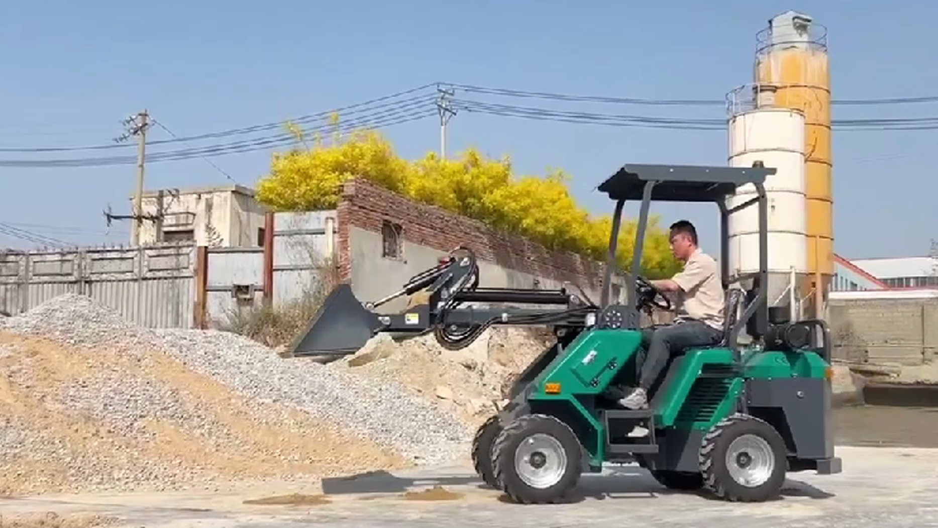
Approach: The operator drives the loader towards the material pile, using the powertrain to control speed.
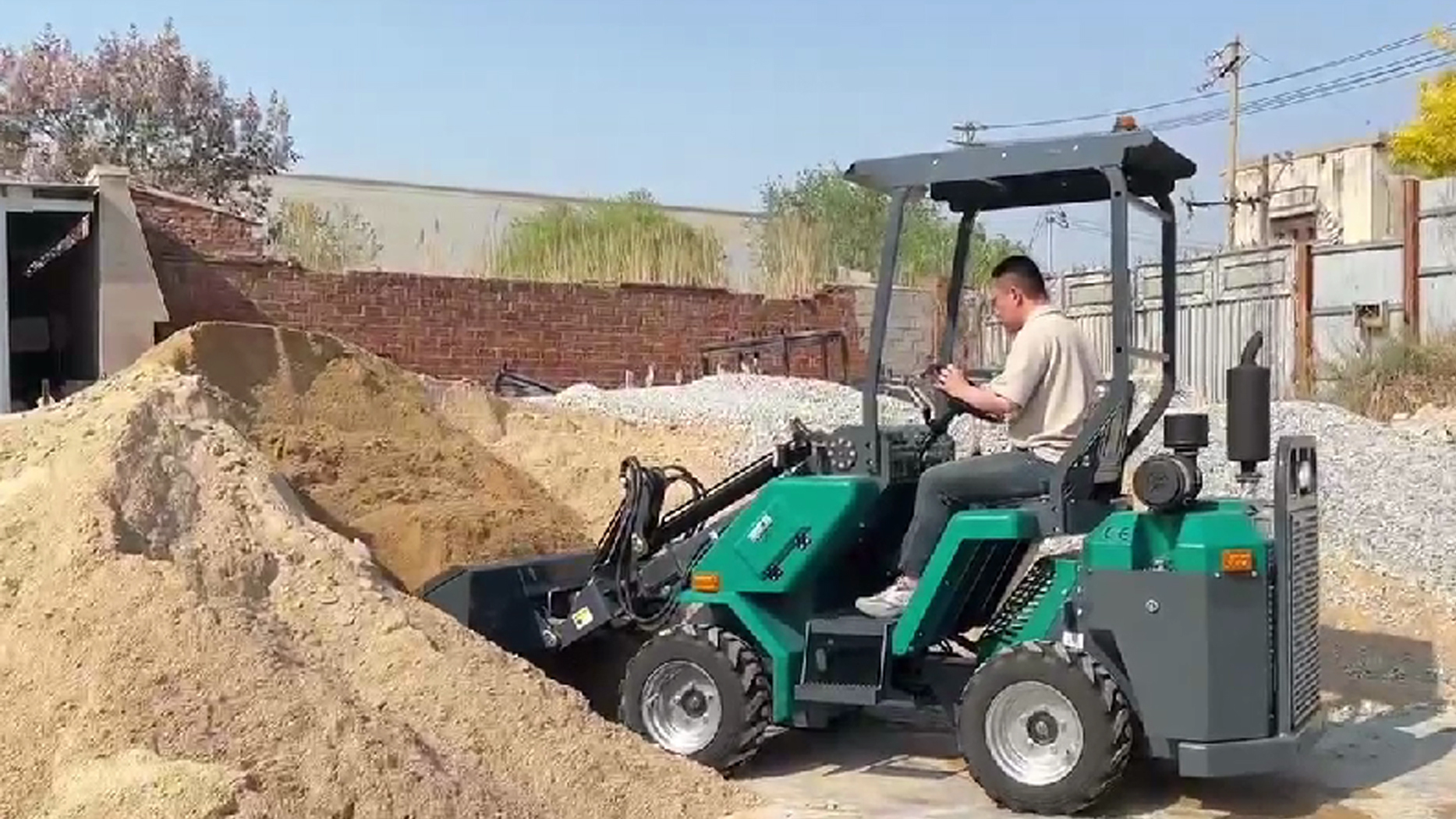
Penetrate: As the loader approaches the pile, the operator lowers the bucket to the ground and drives into the material. Simultaneously, the hydraulic system is engaged to begin curling the bucket back (using tilt cylinders) while slightly lifting the boom (using lift cylinders). This coordinated action, known as "digging," is crucial for efficient bucket filling.
Load: Once the bucket is full, the operator stops the forward motion, continues to lift the boom, and curls the bucket further back to secure the load and prevent spillage during transport.
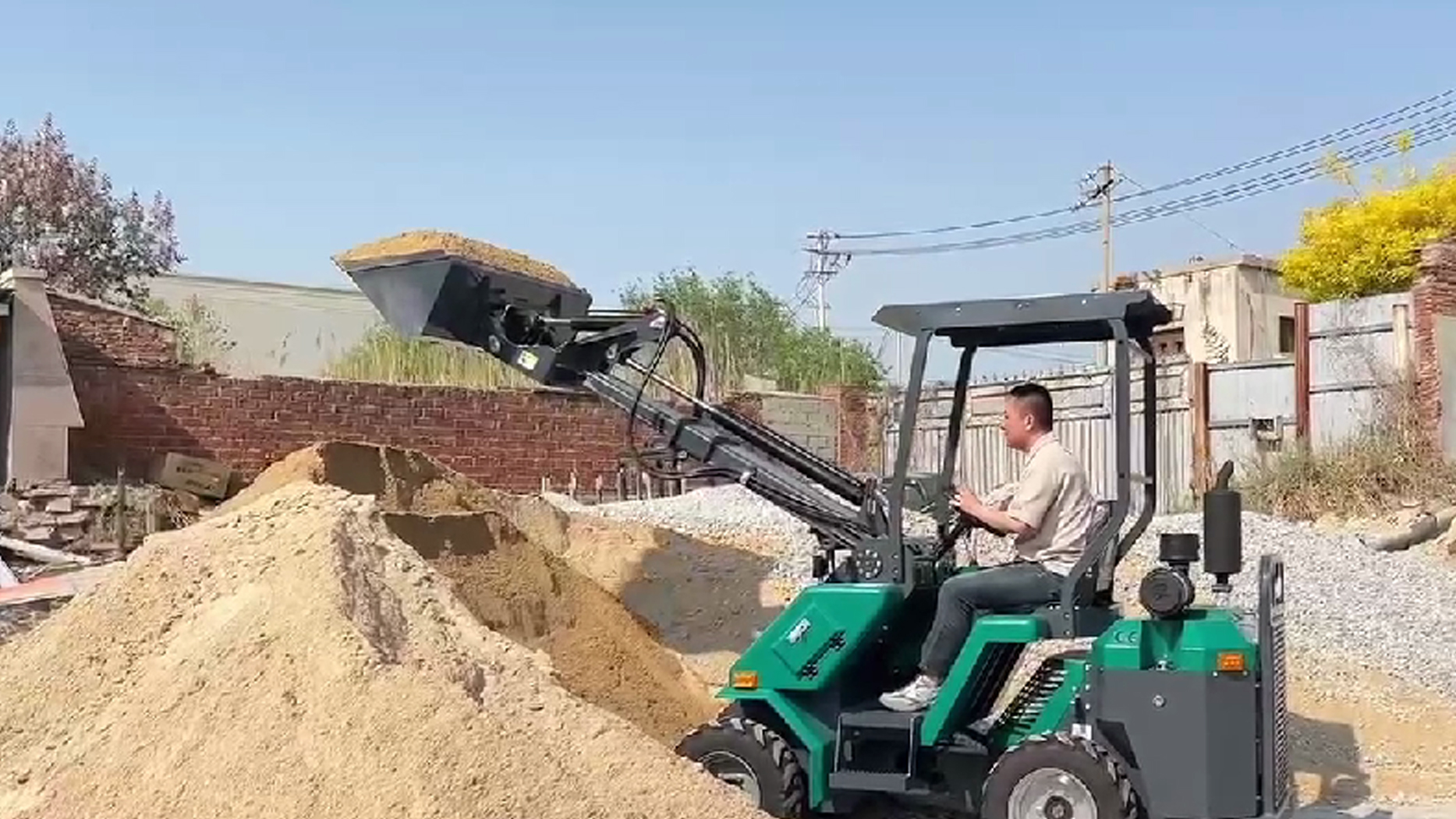
Transport: The loader then reverses away from the pile and transports the material to the dump point (e.g., a dump truck or stockpile), with the powertrain maintaining speed and the steering system guiding its path.
Dump: At the destination, the operator raises the boom to the required height and then uses the hydraulic tilt cylinders to "dump" the material out of the bucket.
Return: The loader then reverses and returns to the pile, lowering the boom and resetting the bucket to the "return-to-dig" position, ready for the next cycle.
Conclusion: A Symphony of Power and Precision
In summary, a wheel loader works through a meticulously engineered integration of its core systems. The powerful diesel engine generates the necessary energy, which is then transmitted to the wheels and hydraulic pump via the powertrain. The hydraulic system precisely converts this energy into the immense force required to operate the lift arms and bucket, performing digging, lifting, and dumping actions. Finally, the articulated steering system provides unparalleled maneuverability, allowing the machine to operate effectively in confined spaces.
From the compact agility of a Q36 wheel loader in a landscaping project to the robust power of a b30 wheel loader moving heavy aggregates, the underlying principles of operation remain consistent. This complex interplay of mechanical, hydraulic, and control systems transforms raw power into productive work, making the wheel loader an indispensable and highly efficient machine for shaping and moving the world around us.
Post time:May.23.2025
